Level 7 Plastics Inc. · Jan 2019 – Oct 2021
Double-shaft plastic shredder (v4, production unit)
First stage of the recycling line: a double-shaft shredder adapted from the open-source Precious Plastic design. The third of three builds, following a paper-shredder proof of concept and a small prototype.
My role: Adapted the design, produced all CAD, cut every plate part, and designed the shaft; did the electrical with two other engineers.
Highlights
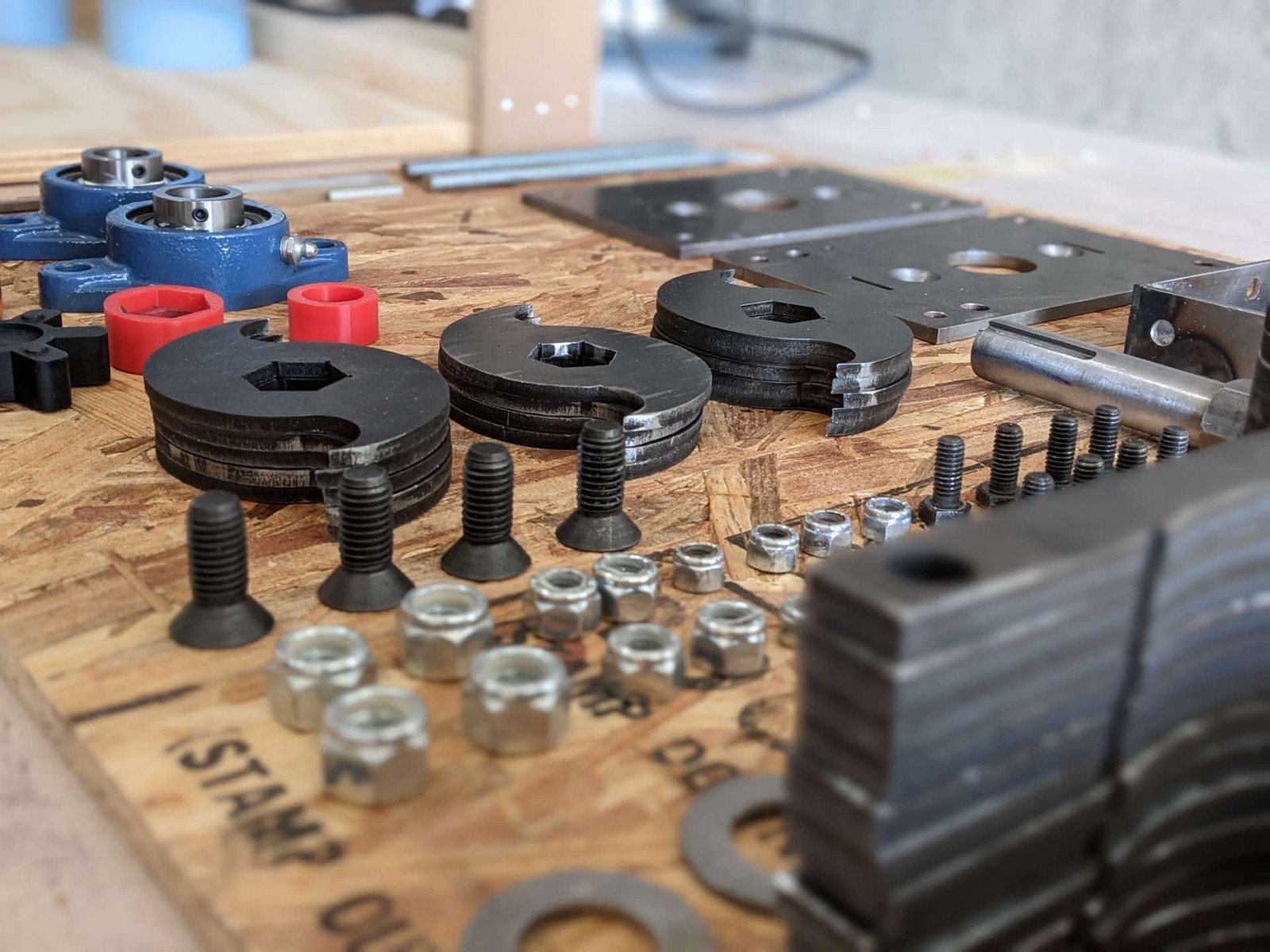
- Adapted the open-source Precious Plastic double-shaft shredder: did all the CAD, cut every plate part on a fibre laser and waterjet, and designed the hex blade shaft, which a machine shop turned and keyed.
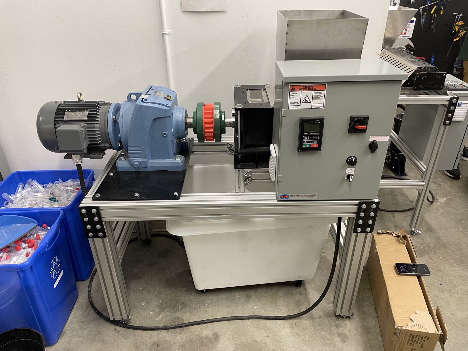
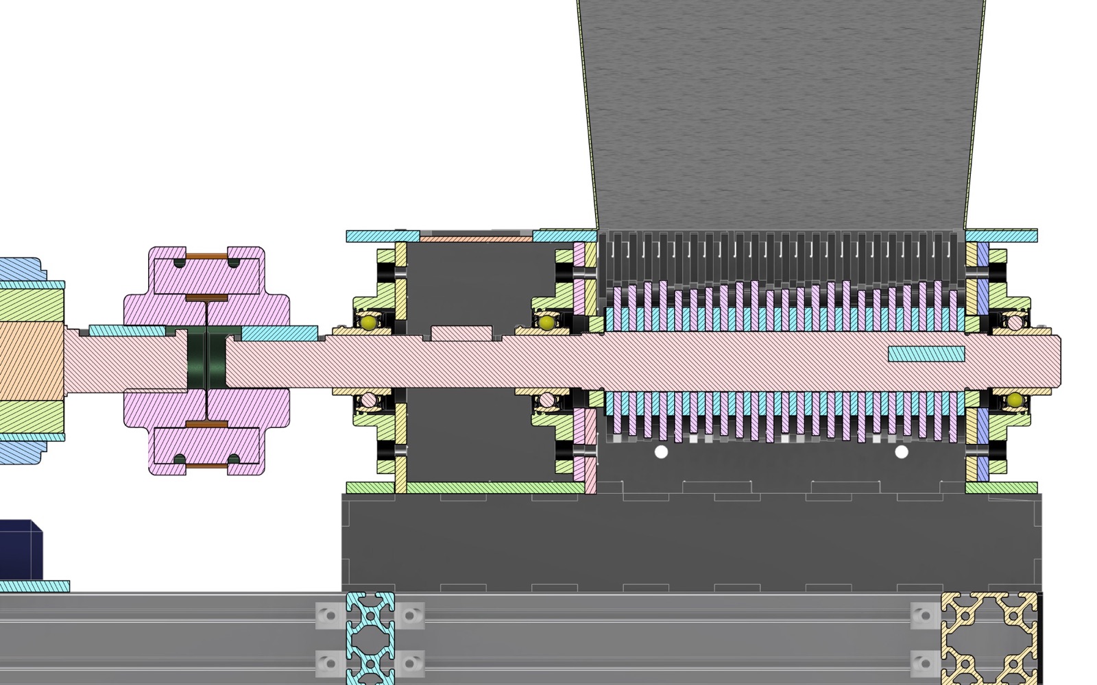
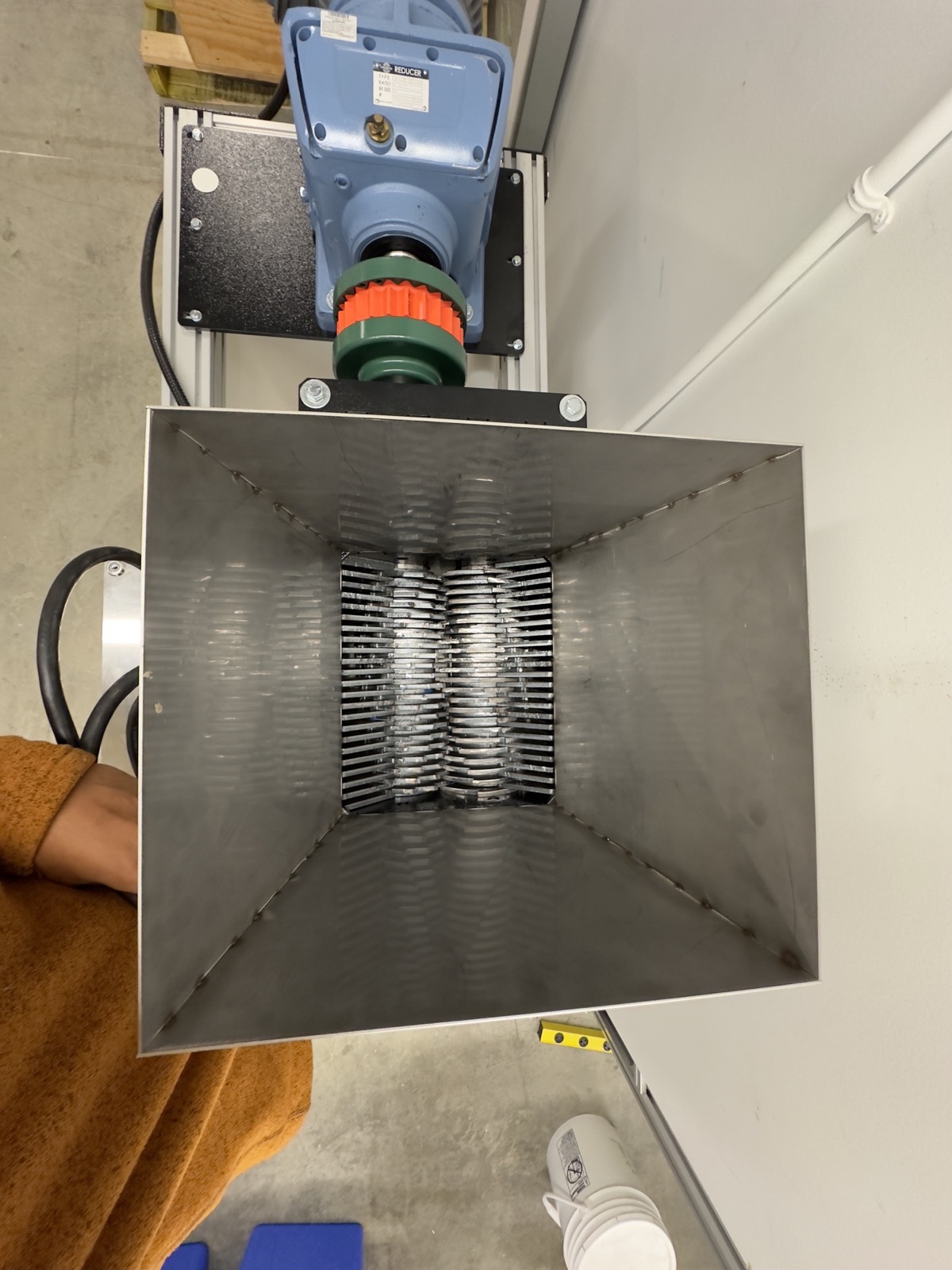
- Drivetrain: ~4 kW gearmotor through a 60:1 helical reducer (~1600 N·m nominal) and a Lovejoy jaw coupling to a keyed hex shaft carrying 6.35 mm waterjet-cut hardened-steel blades.
- Ran the gearmotor on a VFD with an overload relay, reversing switch, and e-stop; cut the first blade set on a plasma cutter for speed, then moved to waterjet when the plasma edges would not hold the stack tolerance.
- Built three shredder iterations, from a paper-shredder proof of concept to the production unit that ran the line.
My contribution
I selected the Precious Plastic double-shaft shredder as the baseline and adapted it, producing all of the CAD and cutting every plate part myself on a fibre laser and a waterjet. I first cut the blades on a plasma cutter, for speed and tighter nesting, and moved them to the waterjet when the plasma edges proved too rough to hold the blade-stack tolerance; the fibre laser could not cut the 6.35 mm blade steel. I designed the shaft, a hex section for the blade stack keyed at one end to a Lovejoy jaw coupling, and had it turned and keyed by a machine shop. Another engineer assisted with the welding, and I did the electrical with two other engineers.
This was the third shredder we built, following a paper-shredder proof of concept and a small prototype.
Technical details
Double-shaft design with 6.35 mm (quarter-inch) hardened-steel blades on hex shafts. Drive: a gearmotor of about 4 kW through a 60:1 helical reducer, roughly 1600 N·m nominal at the output shaft and 15–25 rpm, on a 240 V supply drawing about 22 A. These figures are from the specification we worked to at the time. Rated throughput was 10–50 kg/h depending on material.
Controls: VFD, overload relay, reversing switch, and e-stop. Jams were cleared by reversing manually.
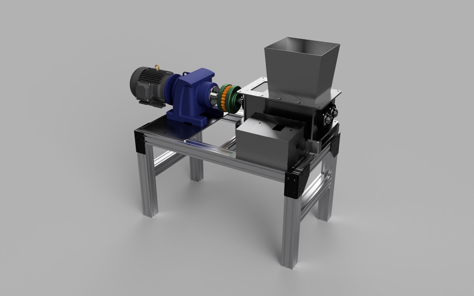
Layout, from the Fusion 360 master assembly (v4): an aluminium-extrusion table carries the shredder box and a riser sub-assembly that lifts the motor and reducer to shaft height; a coupling sub-assembly joins the reducer to the long shaft; long and short shaft sub-assemblies (45 mm diameter) carry the blade stacks on UCFL 209 flange-mount bearings; a sheet-steel hopper sits on the box, and a separate electronics box houses the controls. A magnetic shredder tray sits below the box.
Lessons learned
- Plasma-cut blades were too rough to hold the blade-stack tolerance; we recut them on the waterjet.
- The machine was difficult to service: minor changes often required a full teardown. Lesson: design for service access and modular subassemblies from the start.
- The UCFL 209 bearings were too long to fit inside the shredder box as designed, so I ground back the inner-ring collars to fit. Lesson: check purchased-part envelopes against the enclosure before cutting plate.
Tools and processes
- Materials
- hardened steel blades; steel plate shredder box and spacers; aluminium extrusion table frame; sheet-steel hopper
- Loads
- nominal output torque ~1600 N·m at 15–25 rpm
- Motors and drives
- ~4 kW gearmotor with 60:1 helical reducer; 240 VAC; ~22 A; Lovejoy jaw coupling to a keyed shaft; motor and reducer on a raised riser sub-assembly
- Tolerances
- plasma-cut blades were not clean enough for the blade stack; switched to waterjet; UCFL 209 bearing collars ground back on an angle grinder to fit inside the box
- Processes
- CAD assembly modelling in Fusion 360; fibre laser cutting (frame plate); waterjet cutting (blades; 6.35 mm steel); plasma cutting (early blades; abandoned); welding (assisted by another engineer); turning and keyway cutting (outsourced machine shop)
- Tools
- Fusion 360 (master assembly v4 with table; riser; box; electronics box; motor/gearbox; long and short shaft; coupling; and hopper sub-assemblies); fibre laser cutter; waterjet; plasma cutter; VFD; overload relay; reversing switch; e-stop
Key figures
| Shredder units built (paper-shredder proof of concept, small prototype, production unit) | 3 units |
|---|---|
| Blade thickness (plate) | 6.35 mm |
| Blade shaft diameter (UCFL 209 bearing bore) | 45 mm |
| Gearmotor nominal power | about 4 kW |
| Reducer ratio (helical) | about 60 :1 |
| Nominal output torque | about 1,600 N·m |
| Output shaft speed | about 15–25 rpm |
| Supply | about 240 VAC |
| Current draw | about 22 A |
| Throughput (varies by material) | about 10–50 kg/h |
Part of Level 7 Plastics Inc..